Power Supply (PS)
The main function of the power supply is to convert the voltage coming from the generator to an higher voltage that is suitable for long distance transmission.
Reason:
The current is the same along the whole length of the transmission cable, therefore the idea is to keep it's value as low as possible so that in relationship to the fixed resistance of the transmission path, as low amount of power as possible will be lost along the way from the SHE to the farthest user.
Standard voltage levels for transmission lines are somewhere in the range between 1500vac and 25000vac so that the current will be low.
The main thing to bare in mind is that the transmission voltage can not be so high that a Faraday Cage is required in order to touch the insulation of the conductor.
That means transforming the voltage coming from the generator up to the required transmission level.
Any suitable power pack, including solar panels, can be used to startup the system by providing power to the control electronics, valves, pumps and motors.
Regulating the Electrical Output Power
In App. Diagram 3 or App. Diagram 10, a voltage is fed back from the output of the Power Supply that is used to regulate the opening of the valve Dir-V1.
In App. Diagram 3 or App. Diagram 10, the opening of the valves B-V1 and IS-V1 as well as the speed of the pump HTP4 are regulated by a voltage that comes from the output of the Power Supply.
Changes in the position of B-V1 and IS-V1 as well as the speed of HTP4 are delayed in relationship to Dir-V1 according to the amount of liquid in the Burner/Heat Intake as well as it's temperature.
Safe Control Circuitry
App Diagram 5
When one us dealing with temperature and pressure, there are some precautions that should be taken in order to make doubly sure that nothing will happen and the necessary feedback to operators is available.
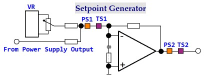
App Diagram 5 is a circuit that increases the safety margin during operation of a SHE or VHE.
VR: Voltage Reference - Used to set the start point of the electric power producing equipment.
PS1. PS2: Pressure Sensor - Used to turn off the Set Point input value to B-V1, IS-V1, HTP4 and Dir-V1, if the pressure in the Burner/Heat Intake liquid chamber goes out of range.
TS1, TS2: Temperature Sensor - Used to turn off the Set Point input value to B-V1, IS-V1, HTP4 and Dir-V1, if the temperature in the Burner/Heat Intake liquid chamber goes out of range.
PS2 and TS2 will also turn off B-V1, IS-V1, HTP4 and Dir-V1, if the amplifier output value goes out of range.
Trains will contain their own vehicle control equipment, whereby acceleration power is taken from batteries that are charged when the train is moving at a constant speed that is below it's absolute maximum.
Trucks and cars will contain their own vehicle control equipment, whereby acceleration power is taken from batteries that are charged when the vehicle is moving at a constant speed that is below it's absolute maximum.
When dealing with electric road vehicles, it is essential that one does not under estimate the requirements for their safe operation.
The main function of the power supply is to convert the voltage coming from the generator to an higher voltage that is suitable for long distance transmission.
Reason:
The current is the same along the whole length of the transmission cable, therefore the idea is to keep it's value as low as possible so that in relationship to the fixed resistance of the transmission path, as low amount of power as possible will be lost along the way from the SHE to the farthest user.
Standard voltage levels for transmission lines are somewhere in the range between 1500vac and 25000vac so that the current will be low.
The main thing to bare in mind is that the transmission voltage can not be so high that a Faraday Cage is required in order to touch the insulation of the conductor.
That means transforming the voltage coming from the generator up to the required transmission level.
Any suitable power pack, including solar panels, can be used to startup the system by providing power to the control electronics, valves, pumps and motors.
Regulating the Electrical Output Power
In App. Diagram 3 or App. Diagram 10, a voltage is fed back from the output of the Power Supply that is used to regulate the opening of the valve Dir-V1.
In App. Diagram 3 or App. Diagram 10, the opening of the valves B-V1 and IS-V1 as well as the speed of the pump HTP4 are regulated by a voltage that comes from the output of the Power Supply.
Changes in the position of B-V1 and IS-V1 as well as the speed of HTP4 are delayed in relationship to Dir-V1 according to the amount of liquid in the Burner/Heat Intake as well as it's temperature.
Safe Control Circuitry
App Diagram 5
When one us dealing with temperature and pressure, there are some precautions that should be taken in order to make doubly sure that nothing will happen and the necessary feedback to operators is available.
App Diagram 5 is a circuit that increases the safety margin during operation of a SHE or VHE.
VR: Voltage Reference - Used to set the start point of the electric power producing equipment.
PS1. PS2: Pressure Sensor - Used to turn off the Set Point input value to B-V1, IS-V1, HTP4 and Dir-V1, if the pressure in the Burner/Heat Intake liquid chamber goes out of range.
TS1, TS2: Temperature Sensor - Used to turn off the Set Point input value to B-V1, IS-V1, HTP4 and Dir-V1, if the temperature in the Burner/Heat Intake liquid chamber goes out of range.
PS2 and TS2 will also turn off B-V1, IS-V1, HTP4 and Dir-V1, if the amplifier output value goes out of range.
Trains will contain their own vehicle control equipment, whereby acceleration power is taken from batteries that are charged when the train is moving at a constant speed that is below it's absolute maximum.
Trucks and cars will contain their own vehicle control equipment, whereby acceleration power is taken from batteries that are charged when the vehicle is moving at a constant speed that is below it's absolute maximum.
When dealing with electric road vehicles, it is essential that one does not under estimate the requirements for their safe operation.