VHE Heat Transfer Buffer (HTB7)
Heat Exchanger Examples
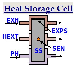
HTB7 is an heat transfer buffer, that collects and stores heat until an optimum amount is reached and then that heat is transferred to another place.
App. Diagram 7
Main Parts:
EXH (input) Exhaust Heat
PH (input) Propellant Heat
HEXT (output) Heat Extraction
EXPS Expansion Space
SS Solar Salt in oil
SEN Temperature Sensor
Each of the cells is immersed in the same oil container, so that good heat exchange between all internal parts is achieved.
You may have a simpler solution that is less material intensive.
Because of it's high specific heat, using a container that only contains Glycerol is also a solution to be considered, which would simplify the design dramatically.
HTB7 Description:
In App. Diagram 10, the Burner has a fossil fuel inlet that is the primary energy supply to the system.
Vapor (steam or alcohol) is used as the propellant to drive the Turbine.
Alcohol vapor means 20% higher vapor pressure or 20% more vapor through put rate is used.
Water vapor is the one that every one likes to use, because it is the most documented.
Water vapor requires an high temperature, which means that a lot of extra heat is generated that may not be usable, if there is no secondary stage for it.
For this description, the minimum water vapor temperature is defined here to be 217°C.
For an alcohol as propellant, the minimum vapor temperature is defined here to be 187°C.
For the VHE, the combustion material in the Burner is oil or gas.
Black iron pipes and high temperature silicon will keep gas leaks at bay.
With good insulation of the Burner, the temperature of the gasses coming through it's exhaust can be between 200°C and 600°C, therefore if that heat is to be reused, keep the distance between the Burner and HTB7 as short as possible.
Use an heat insulating separator between two sections of the exhaust, so that conduction losses by way of the exhaust material will not cause heat losses that propagate back to the burner.
In App. Diagram 10, the temperature of HTB7 is defined to be somewhere around 150ºC-190ºC, so that full advantage can be taken of the heat storage capacity of the material that are also called HITEC Molten Salt.
In App. Diagram 10 their use will allow the two different temperatures from the Burner exhaust and the turbine outlet to be mixed and produce an output temperature at V10 that is a little lower than any of the two input temperatures.
By connecting the two different heat sources to opposite ends of the storage containers, the heat will propagate from both ends and meet in the middle of a storage section.
The stored heat is then extracted using the connection in the middle of the section.
Extracting Heat from the Exhaust using HTB7 as an Intermediate Storage
1. Heat conductivity of iron: 80.2 W/ (m·K)
Heat conductivity of mild steel: 45 W/(m.K) Heat conductivity of graphite: 200-500 W/(m.K).
Heat conductivity of copper: 398 W/(m.K)
Heat conductivity of aluminum: 235 W/(m.K)
Tensile Strength mild steel:
440 N/mm² = 440 Mpa = 44kg/mm²
Tensile Strength copper: 210MPa = 21kg/mm²
Tensile Strength aluminum: 90MPa = 9kg/mm²
2. After all studies and circumstances have been weighed and considered, an optimized material choice for the compartments that hold the solar salt will probably be mild steel.
3. If excess heat is sent through I/O-1 or I/O-2 that is used for other applications such as to sterilize food products, the receiver of the heat can have their own heat storage that is made similar to HTB7.
Barium Hydroxide Ba(OH)2
Heat Storage Capacity: 655MJ/m³
Melting Point: 78ºC
Boiling Points: 780ºC in octahydrate form
Boiling Points: 300ºC in monohydrate form
Boiling Points: 400ºC in anhydrous form
Weight: 3,74 g/cm³
What Others are Thinking
Output Heat Destination:
If the heat in the vapor coming from the output of the Turbine is to be collected by an heat conducting liquid that passes through HTB7, V14, JP, HTP2 and V13, whereby it works as a refrigerant that cools down the vapor to a liquid, then check out the content of the page Vaporized Heat Collection Types.
The heat conductor comes through V14, collects the heat from (JP), whereby it will expand and then be compressed using HTP2, so that it reenters HTB7 through V13 and gives up the collected heat at an higher temperature inside of it.
The turbine propellant vapor that has been thereby relieved of it's heat, is then pumped back into the Burner liquid chamber as a liquid by the Jacket Pump (JP).
Heat Exchanger Examples
HTB7 is an heat transfer buffer, that collects and stores heat until an optimum amount is reached and then that heat is transferred to another place.
App. Diagram 7
Main Parts:
EXH (input) Exhaust Heat
PH (input) Propellant Heat
HEXT (output) Heat Extraction
EXPS Expansion Space
SS Solar Salt in oil
SEN Temperature Sensor
Each of the cells is immersed in the same oil container, so that good heat exchange between all internal parts is achieved.
You may have a simpler solution that is less material intensive.
Because of it's high specific heat, using a container that only contains Glycerol is also a solution to be considered, which would simplify the design dramatically.
HTB7 Description:
In App. Diagram 10, the Burner has a fossil fuel inlet that is the primary energy supply to the system.
Vapor (steam or alcohol) is used as the propellant to drive the Turbine.
Alcohol vapor means 20% higher vapor pressure or 20% more vapor through put rate is used.
Water vapor is the one that every one likes to use, because it is the most documented.
Water vapor requires an high temperature, which means that a lot of extra heat is generated that may not be usable, if there is no secondary stage for it.
For this description, the minimum water vapor temperature is defined here to be 217°C.
For an alcohol as propellant, the minimum vapor temperature is defined here to be 187°C.
For the VHE, the combustion material in the Burner is oil or gas.
Black iron pipes and high temperature silicon will keep gas leaks at bay.
With good insulation of the Burner, the temperature of the gasses coming through it's exhaust can be between 200°C and 600°C, therefore if that heat is to be reused, keep the distance between the Burner and HTB7 as short as possible.
Use an heat insulating separator between two sections of the exhaust, so that conduction losses by way of the exhaust material will not cause heat losses that propagate back to the burner.
In App. Diagram 10, the temperature of HTB7 is defined to be somewhere around 150ºC-190ºC, so that full advantage can be taken of the heat storage capacity of the material that are also called HITEC Molten Salt.
In App. Diagram 10 their use will allow the two different temperatures from the Burner exhaust and the turbine outlet to be mixed and produce an output temperature at V10 that is a little lower than any of the two input temperatures.
By connecting the two different heat sources to opposite ends of the storage containers, the heat will propagate from both ends and meet in the middle of a storage section.
The stored heat is then extracted using the connection in the middle of the section.
Extracting Heat from the Exhaust using HTB7 as an Intermediate Storage
1. Heat conductivity of iron: 80.2 W/ (m·K)
Heat conductivity of mild steel: 45 W/(m.K) Heat conductivity of graphite: 200-500 W/(m.K).
Heat conductivity of copper: 398 W/(m.K)
Heat conductivity of aluminum: 235 W/(m.K)
Tensile Strength mild steel:
440 N/mm² = 440 Mpa = 44kg/mm²
Tensile Strength copper: 210MPa = 21kg/mm²
Tensile Strength aluminum: 90MPa = 9kg/mm²
2. After all studies and circumstances have been weighed and considered, an optimized material choice for the compartments that hold the solar salt will probably be mild steel.
3. If excess heat is sent through I/O-1 or I/O-2 that is used for other applications such as to sterilize food products, the receiver of the heat can have their own heat storage that is made similar to HTB7.
Barium Hydroxide Ba(OH)2
Heat Storage Capacity: 655MJ/m³
Melting Point: 78ºC
Boiling Points: 780ºC in octahydrate form
Boiling Points: 300ºC in monohydrate form
Boiling Points: 400ºC in anhydrous form
Weight: 3,74 g/cm³
What Others are Thinking
Output Heat Destination:
If the heat in the vapor coming from the output of the Turbine is to be collected by an heat conducting liquid that passes through HTB7, V14, JP, HTP2 and V13, whereby it works as a refrigerant that cools down the vapor to a liquid, then check out the content of the page Vaporized Heat Collection Types.
The heat conductor comes through V14, collects the heat from (JP), whereby it will expand and then be compressed using HTP2, so that it reenters HTB7 through V13 and gives up the collected heat at an higher temperature inside of it.
The turbine propellant vapor that has been thereby relieved of it's heat, is then pumped back into the Burner liquid chamber as a liquid by the Jacket Pump (JP).