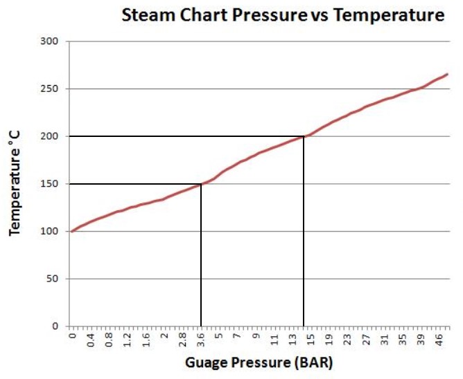
Propellant Vapor and Pressure
Latent Heat Water
1. Propellant Specific Heat Specific Heat
liquid Vapor
Water 4.2 kj/(kg.°K) 2.2 kj/(kg.°K).
Alcohol 2.2 kj/(kg.°K) 1.6 kj/(kg.°K)
2. Temperature drop inside the turbine chamber = 50°K.
Alcohol Vapor = ethanol, rum, palm alcohol etc.There alcohols that can operate up to 325°C.
3. Propellant Energy in 1kg vapor/s
This means that only 50 degrees will be extracted from the vapor.
Water Vapor 2.2 kj/(kg.°K) * 50°K = 110kj = 110kw.
Alcohol Vapor 1.6 kj/(kg.°K) * 50°K = 80kj = 80kw
(2,2e3/1,6e3) * 1,6e3 * 50 = 110kj = 110kw
(2,2e3/1,6e3) = 1.375 more alcohol vapor is required for the same amount of energy extraction by the turbine.
4. Propellant Liquid Volume to Weight Power
Water Liquid 1liter/s = 1kg/s vapor 110kw
Alcohol Liquid 1.375liter/s = 1kg/s vapor 110kw
5. Make the amount of liquid required in order to keep a constant pressure of 22 bar at the water vapor output of the Burner equal to at least somewhere between 100 and 1000 times the amount needed per second, so that power extraction can be continuous, without any drop in pressure. Double that amount for an alcohol.
6. Liquid Specific cp Energy
Propellant Pressure Temp. Heat (kWh/(kg * K))
Water 22 bar 217°C 3.1kj/(kg.°K)
Alcohol 22.92 bar 187°C 3.2kj/(kg.°K) 0.000888
cp is at constant pressure.
7. Assume that in the turbine chamber, the vapor will loose 50°K and come out at a temperature of about 167°C and 137°C.
8. Water vapor exiting the turbine chamber would need to loose 167°C - 100°C = 67°K at the Jacket Pump (JP), before it is pumped back into the liquid chamber of the Burner/Heat Intake.
9. Alcohol vapor exiting the turbine chamber would need to loose 137°C - 98°C = 37°K at the Jacket Pump (JP), before it is pumped back into the liquid chamber of the Burner/Heat Intake.
10. It is the job of the jacket pump or suitable variations of it, to convert the vapor that exits the turbine to liquid and pump it back into the liquid chamber of the burner.
11. Note that both versions of the Heat Engine as shown in Diagram 2 and Diagram 10, put the heat that is extracted at the Jacket Pump (JP) to an alternative use or back into the Heat Storage (HS) that is provided for that purpose.