Absorber Tube
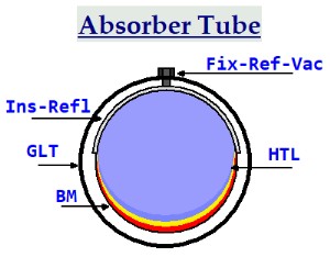
App. Diagram 8
Ins-Refl - Insulating Reflector:
Reflects heat back to the steel tube and prevents heat loss through radiation at the back of the tube. This could be aluminum foil on the inner surface of the glass tube.
GLT - Glass Tube:
Reduces heat loss to the atmosphere through conduction.
BM - Black Metal (Fe, Steel, Al, Cu) tube: Carries the heat transfer liquid. Iron may be the cheapest and good enough. Solkote black paint coating (-73°C to +538°C)
HTL - Heat Transfer Liquid: Absorbs and moves the heat out of the solar concentrator.
Heat transfer Coefficients:
Glycerol = 786 W/(m²·ºK)
Thermal oils = 1kw/(m².ºK) to 3.5kw/(m².ºK)
Fix-Ref-Vac - Fixing: Fixes the reflector inside the glass tube and also used as an outlet to build a vacuum inside the glass tube in order to reduce heat loss through conduction. It can be welded or brazed onto the black metal tube. Others may choose to use this inlet to insert krypton gas (kr) 0.00943 W/(m·K), that will act as an insulator, into the space between the glass tube and the black metal receiver.
Example Energy Collection
W = Ws = Js.
1000W = 1kWs = 1kJs
Heat Absorber Calculation for Parabolic Trough Concentrator (PTC)
It is assumed here that one solar concentrator unit will be 2m wide and 4m long = 8m²
Number of Collectors = 44.44m²/ 8m² = 6 collectors @ 4m length each.
Total Length of Collector Absorber Tube = 6 * 4m = 24m
Tin - temperature in ºC
Tout - temperature out ºC
Heat conductance - W/m.ºK
U - Heat Transfer Coefficient W/m².ºK
Tin1 = 237ºC
Tout1 = 287ºC
Tin2 = 227ºC
Tout2 = 237ºC
dT1 = 287ºC - 237ºC = 50ºK
dT2 = 227ºC - 237ºC = 10ºK
U Glycerol = 786 W/(m²·K)
U Thermal Oils = 1kw/(m².ºK) to 3.5kw/(m².ºK)
A - Heat Transfer Area
Q - Amount of Heat in W
Q = U*A*(dT)
From HTB Table 1 Parabolic Trough Concentrator (PTC)
Concentration Factor Cf: 22.75
Absorber Tube Radius R: 0.035m
A. Half Circumference of Absorber Tube Hc: pi*R = pi * 0.035m = 0.11m
B. Effective Area Absorber Tube A = width * length = 0.11m * 24m = 2.64m²
C. Solar Concentration Factor Cf = Solar Concentrator Area/Area Absorber Tube Area = 44.44m²/2.64m² = 16.83
Glycerol
Q for dT1 = 786W/(m²·K) * 2.64m² *50ºK = 103.75kw
Q for dT2 = 786W/(m²·K) * 2.64m² *10ºK = 20.75kw
Connect troughs in series in order to increase the output temperature of the parabolic trough concentrator.
Energy Collection Capability 2400kwh/day Using Glycerol and Thermal Oil
From Design Strategy it was estimated that:
2400kwh/day would be required in order to transport 4800persons/day on a round trip that is a distance of 50km and 1066.6m² of solar concentrator area would be required in order to collect that amount of energy from solar radiation.
Q = U*A*(dT)
Assuming that the solar concentrator can increase the temperature of the liquid coming in by 50ºK.
Area per concentrator unit will be 2m wide and 4m long = 8m²
Number of Collectors = 1066.6m²/ 8m² = 134 trough collectors @ 4m length each.
Total Length of Absorber Tube = 134 * 4 = 533.3m
Absorber Tube radius R = 0.035m
Absorber Tube half circumference = pi*R = 0.11m
Radiation Acceptance Area of Absorber Tube A = 0.11m * 533.3m = 58.66m²
Glycerol 50K Temperature Change
Q = U*A*(Tin-Tout)
Qg = 786 W/(m²·K) * 58.66m² * 50K = 2.3053Mws = 640Wh
Thermal Oil 50K Temperature Change
Qt = 3.5kW/(m²·K)*58.66m² * 50K = 10.266Mws = 2.852kWh
The result shows that the size (SHE) that is being talked about in the text can be run using the parameters and sizes provided.
Your best path is to build your own small version, make the necessary measurements and size adjustments and then scale up the result.
The heat absorption capacity together with the real time it takes the heat conductor to move though the absorber tube while it is collecting heat will influence the real result.
The concentration factor can be increased by reducing the size of the the absorber tube or increasing the size of the concentrator area.
Tracking accuracy will become more relevant as the cross section of the absorber tube decreases.
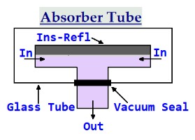
App. Diagram 9
App. Diagram 9 shows the absorber tube in length cross section.
In the diagram, the tube is fed with heat conducting liquid from both ends at the same time.
The joint might be between two troughs.
The said heat conductor is then extracted in the middle of the tube using a larger diameter tube and sent to the heat exchanger in the heat storage.
The pump that pumps the heat conductor through the absorber tube is constructed so that it can pump varying amounts as the need arises.
The other alternative would be to use a synchronous motor to drive the liquid circulation pump in start/Stop mode.
When using blackened steel or iron pipes for this job, insert something into the tube that will cause a turbulent liquid flow that will increase the heat transfer rate from the pipe to the liquid.
If the absorber tube bends during normal operation, it will loose efficiency.
A Focal Point Calculation
Black Iron Oxide
Flexible Pipe for 400°C
The Fire Hazard
App. Diagram 8
Ins-Refl - Insulating Reflector:
Reflects heat back to the steel tube and prevents heat loss through radiation at the back of the tube. This could be aluminum foil on the inner surface of the glass tube.
GLT - Glass Tube:
Reduces heat loss to the atmosphere through conduction.
BM - Black Metal (Fe, Steel, Al, Cu) tube: Carries the heat transfer liquid. Iron may be the cheapest and good enough. Solkote black paint coating (-73°C to +538°C)
HTL - Heat Transfer Liquid: Absorbs and moves the heat out of the solar concentrator.
Heat transfer Coefficients:
Glycerol = 786 W/(m²·ºK)
Thermal oils = 1kw/(m².ºK) to 3.5kw/(m².ºK)
Fix-Ref-Vac - Fixing: Fixes the reflector inside the glass tube and also used as an outlet to build a vacuum inside the glass tube in order to reduce heat loss through conduction. It can be welded or brazed onto the black metal tube. Others may choose to use this inlet to insert krypton gas (kr) 0.00943 W/(m·K), that will act as an insulator, into the space between the glass tube and the black metal receiver.
Example Energy Collection
W = Ws = Js.
1000W = 1kWs = 1kJs
Heat Absorber Calculation for Parabolic Trough Concentrator (PTC)
It is assumed here that one solar concentrator unit will be 2m wide and 4m long = 8m²
Number of Collectors = 44.44m²/ 8m² = 6 collectors @ 4m length each.
Total Length of Collector Absorber Tube = 6 * 4m = 24m
Tin - temperature in ºC
Tout - temperature out ºC
Heat conductance - W/m.ºK
U - Heat Transfer Coefficient W/m².ºK
Tin1 = 237ºC
Tout1 = 287ºC
Tin2 = 227ºC
Tout2 = 237ºC
dT1 = 287ºC - 237ºC = 50ºK
dT2 = 227ºC - 237ºC = 10ºK
U Glycerol = 786 W/(m²·K)
U Thermal Oils = 1kw/(m².ºK) to 3.5kw/(m².ºK)
A - Heat Transfer Area
Q - Amount of Heat in W
Q = U*A*(dT)
From HTB Table 1 Parabolic Trough Concentrator (PTC)
Concentration Factor Cf: 22.75
Absorber Tube Radius R: 0.035m
A. Half Circumference of Absorber Tube Hc: pi*R = pi * 0.035m = 0.11m
B. Effective Area Absorber Tube A = width * length = 0.11m * 24m = 2.64m²
C. Solar Concentration Factor Cf = Solar Concentrator Area/Area Absorber Tube Area = 44.44m²/2.64m² = 16.83
Glycerol
Q for dT1 = 786W/(m²·K) * 2.64m² *50ºK = 103.75kw
Q for dT2 = 786W/(m²·K) * 2.64m² *10ºK = 20.75kw
Connect troughs in series in order to increase the output temperature of the parabolic trough concentrator.
Energy Collection Capability 2400kwh/day Using Glycerol and Thermal Oil
From Design Strategy it was estimated that:
2400kwh/day would be required in order to transport 4800persons/day on a round trip that is a distance of 50km and 1066.6m² of solar concentrator area would be required in order to collect that amount of energy from solar radiation.
Q = U*A*(dT)
Assuming that the solar concentrator can increase the temperature of the liquid coming in by 50ºK.
Area per concentrator unit will be 2m wide and 4m long = 8m²
Number of Collectors = 1066.6m²/ 8m² = 134 trough collectors @ 4m length each.
Total Length of Absorber Tube = 134 * 4 = 533.3m
Absorber Tube radius R = 0.035m
Absorber Tube half circumference = pi*R = 0.11m
Radiation Acceptance Area of Absorber Tube A = 0.11m * 533.3m = 58.66m²
Glycerol 50K Temperature Change
Q = U*A*(Tin-Tout)
Qg = 786 W/(m²·K) * 58.66m² * 50K = 2.3053Mws = 640Wh
Thermal Oil 50K Temperature Change
Qt = 3.5kW/(m²·K)*58.66m² * 50K = 10.266Mws = 2.852kWh
The result shows that the size (SHE) that is being talked about in the text can be run using the parameters and sizes provided.
Your best path is to build your own small version, make the necessary measurements and size adjustments and then scale up the result.
The heat absorption capacity together with the real time it takes the heat conductor to move though the absorber tube while it is collecting heat will influence the real result.
The concentration factor can be increased by reducing the size of the the absorber tube or increasing the size of the concentrator area.
Tracking accuracy will become more relevant as the cross section of the absorber tube decreases.
App. Diagram 9
App. Diagram 9 shows the absorber tube in length cross section.
In the diagram, the tube is fed with heat conducting liquid from both ends at the same time.
The joint might be between two troughs.
The said heat conductor is then extracted in the middle of the tube using a larger diameter tube and sent to the heat exchanger in the heat storage.
The pump that pumps the heat conductor through the absorber tube is constructed so that it can pump varying amounts as the need arises.
The other alternative would be to use a synchronous motor to drive the liquid circulation pump in start/Stop mode.
When using blackened steel or iron pipes for this job, insert something into the tube that will cause a turbulent liquid flow that will increase the heat transfer rate from the pipe to the liquid.
If the absorber tube bends during normal operation, it will loose efficiency.
A Focal Point Calculation
Black Iron Oxide
Flexible Pipe for 400°C
The Fire Hazard