Sensors (SENS)
Temperature and pressure sensors as well as over voltage sensors are placed wherever necessary.
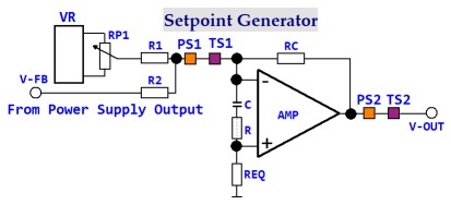
The set point generator is a circuit that uses the stable voltage that comes from the Voltage Reference (VR) to set the control voltage that is inputted to the main control amplifier (AMP).
After it is known that the circuit works, VR is changed to a digital/analog converter whose inputs are fed from an up/down counter that gets it's values from a data bus, so that the output voltage of (VR) can be set from a computer keyboard.
RP1 would still be there and can be used as an emergency hand operated turn on/turn off function.
The amplifier uses that voltage to set the opening of the valve (Dir-V1) shown in App. Diagram 3 and App. Diagram 10.
The output direction of the valve (EXV) is set manually and allows the turbine propellant path to be evacuated, before the system is started.
The voltage (V-FB) is taken from the output of the power supply, whose main voltage goes to the power cable and is used in App. Diagram 6 to regulate the opening of the valve (Dir-V1) shown in App. Diagram 3 and App. Diagram 10 through the output (V-OUT).
In App. Diagram 3, the output of the (AMP) is also used to generate a voltage that is used to control the on/off valves (IS-V1) and (B-V1) as well as the pump HTP3.
App. Diagram 6 shows where two wire sensors are to be placed in order to protect against the rare case when, during normal operation and for undefined reasons, the input voltage at the (-) input of (AMP) changes towards maximum.
Note: That both the input and output contain the sensors, so that when any one of them is activated and becomes a very high resistance, to mean off, the output control voltage at (V-OUT) will be 0.
For basic equilibrium at the differential AMP, the value of REQ is the equivalent resistance of that which is at the (-) input.
In order to compensate for low speed input zero drift caused by temperature drift during normal operation, the R and C combination is placed between the (-) and the (+) inputs.
An open circuit at the RC combination will also cause PS2 and TS2 to activate and turn off the vapor supply to the turbine.
That means that the valve (Dir-V1) shown in App. Diagram 3 and App. Diagram 10 is normally closed.
The same is valid for (IS-V1) and (B-V1) in App. Diagram 3.
Temperature and pressure sensors as well as over voltage sensors are placed wherever necessary.
The set point generator is a circuit that uses the stable voltage that comes from the Voltage Reference (VR) to set the control voltage that is inputted to the main control amplifier (AMP).
After it is known that the circuit works, VR is changed to a digital/analog converter whose inputs are fed from an up/down counter that gets it's values from a data bus, so that the output voltage of (VR) can be set from a computer keyboard.
RP1 would still be there and can be used as an emergency hand operated turn on/turn off function.
The amplifier uses that voltage to set the opening of the valve (Dir-V1) shown in App. Diagram 3 and App. Diagram 10.
The output direction of the valve (EXV) is set manually and allows the turbine propellant path to be evacuated, before the system is started.
The voltage (V-FB) is taken from the output of the power supply, whose main voltage goes to the power cable and is used in App. Diagram 6 to regulate the opening of the valve (Dir-V1) shown in App. Diagram 3 and App. Diagram 10 through the output (V-OUT).
In App. Diagram 3, the output of the (AMP) is also used to generate a voltage that is used to control the on/off valves (IS-V1) and (B-V1) as well as the pump HTP3.
App. Diagram 6 shows where two wire sensors are to be placed in order to protect against the rare case when, during normal operation and for undefined reasons, the input voltage at the (-) input of (AMP) changes towards maximum.
Note: That both the input and output contain the sensors, so that when any one of them is activated and becomes a very high resistance, to mean off, the output control voltage at (V-OUT) will be 0.
For basic equilibrium at the differential AMP, the value of REQ is the equivalent resistance of that which is at the (-) input.
In order to compensate for low speed input zero drift caused by temperature drift during normal operation, the R and C combination is placed between the (-) and the (+) inputs.
An open circuit at the RC combination will also cause PS2 and TS2 to activate and turn off the vapor supply to the turbine.
That means that the valve (Dir-V1) shown in App. Diagram 3 and App. Diagram 10 is normally closed.
The same is valid for (IS-V1) and (B-V1) in App. Diagram 3.
App. Diagram 6